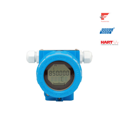
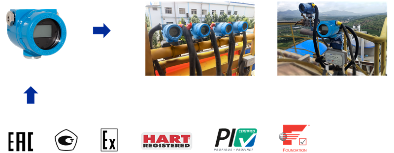
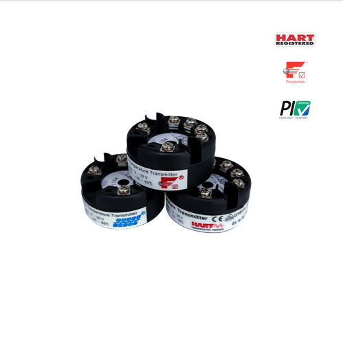
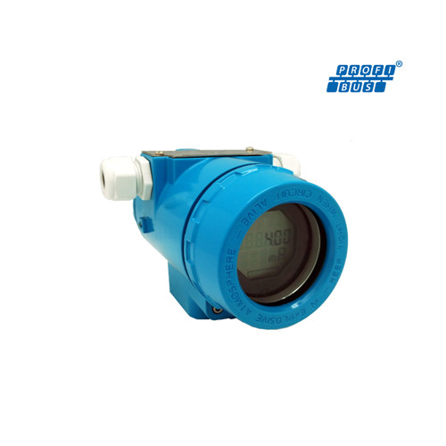
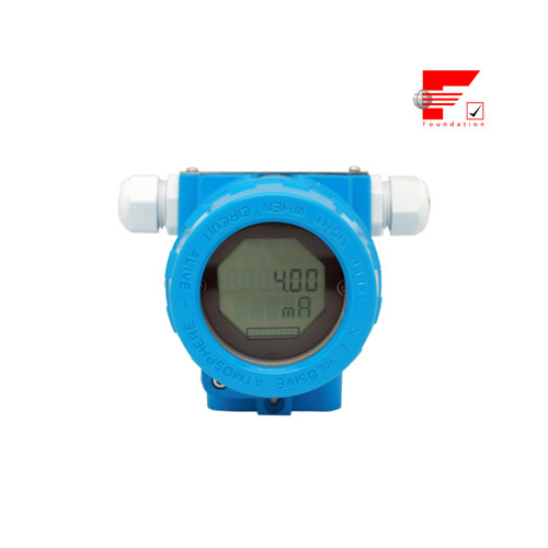
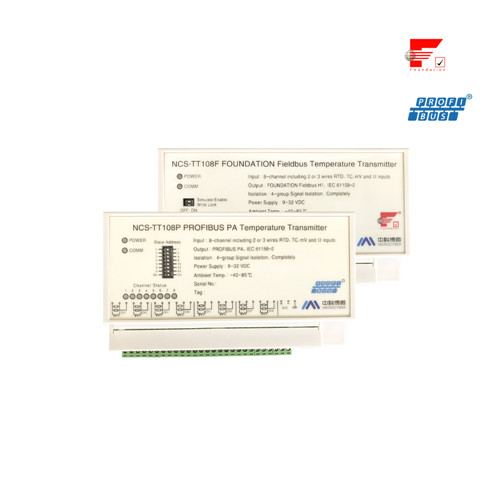
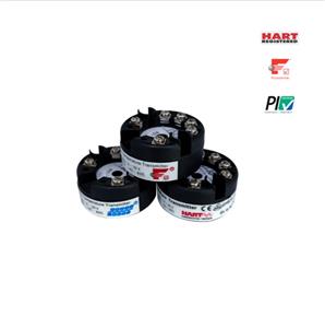
NCS-TT105 Intelligent Temperature Sensors

- : Microcyber
- : Liaoning, China
- : In Stock
- : 500 Sets/Month
NCS-TT105 Intelligent Temperature Sensors:
1. Support the latest versions of FF H1, PROFIBUS PA and HART protocols
2. Support 6 types of thermal resistance and 8 types of thermocouple
3. Support 2-channel sensor input
4. Thermal resistance supports 2-wire, 3-wire and 4-wire
5. The cold end compensation accuracy of thermocouple is ±0.5 ℃
6. High precision (better than grade 0.1), low temperature drift (better than ±50ppm/℃ )
7. Comply with FCG interoperability specification (ITK 6 and HART 7), PNO interoperability test certification
8. (PA profile 3.02)
9. Explosion-proof (intrinsically safe, flameproof) certification
1.Overview
NCS-TT105 Intelligent temperature sensors adopts fieldbus technology, is a new generation of fieldbus smart temperature transmitter, and is an indispensable field device in process control. The device integrates rich functional modules, which can realize both general detection functions and complex control strategies.
NCS-TT105 adopts digital technology, which can be applied to a variety of thermal resistance and thermocouple sensors, with a wide range, simple interface between the field and the control room, and can greatly reduce the cost of installation, operation and maintenance.
NCS-TT105 Intelligent temperature sensors supports HART, FF, PA protocol and can be widely used in petroleum, chemical, power plant, metallurgy and other industries.
The dimensions of the intelligent temperature sensors are shown in the Figure 1.1 below:

Figure 1.1 Dimensions of intelligent temperature sensors (unit: mm)
The general assembly drawing is shown as below:
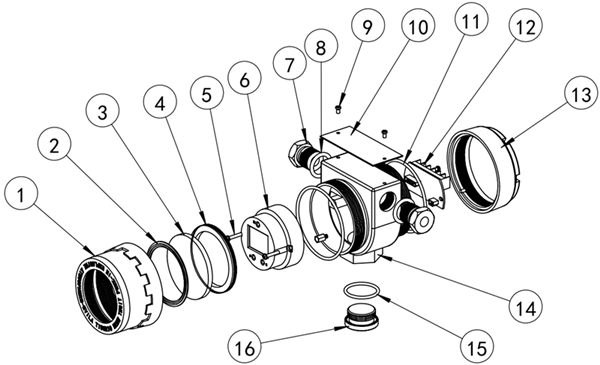
Figure 1.2 The general assembly drawing
No. | Name | Qty | Material | No. | Name | Qty | Material |
1 | Front cover | 1 | ADC12 | 9 | Fastening screw | 2 | 304 SUS |
2 | Glass seal ring | 1 | PC | 10 | Nameplate | 1 | 304 SUS |
3 | Window glass | 1 | PEB | 11 | Seal ring | 2 | NBR |
4 | Glass fastening ring | 1 | ADC12 | 12 | Terminal board | 1 | |
5 | Fastening screw | 2 | 304 SUS | 13 | Back cover | 1 | ADC12 |
6 | Smart temperature module | 1 | 14 | Body housing | 1 | ADC12 | |
7 | Electrical connector | 2 | 304 SUS | 15 | Seal ring | 1 | NBR |
8 | Seal ring | 2 | NBR | 16 | Seal gland | 1 | 304 SUS |
2. Installation
2.1 Transmitter Installation
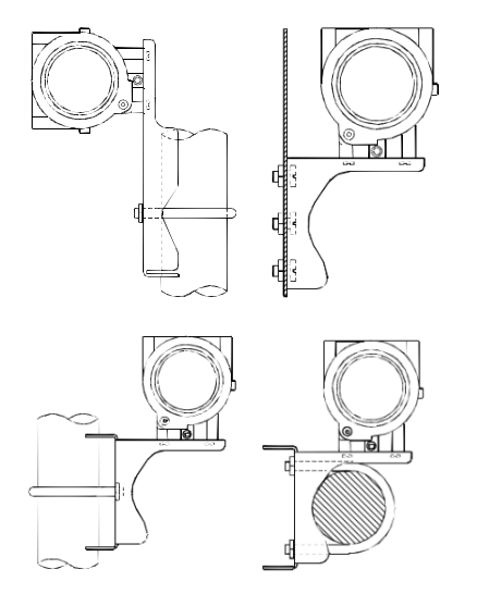
For the installation of NCS-TT105 Intelligent temperature sensors, there are three types of mounting brackets available: tube-mounted flat bracket, tube-mounted curved bracket, and disk-mounted curved bracket. Correspondingly, there are three installation methods, namely flat bracket tube installation, curved bracket plate installation, and curved bracket tube installation. The installation methods are described below:
A typical installation of flat bracket tube installation is shown in Figure 2.1,fix the transmitter on the tube-mounted flat bracket, and then fix the tube-mounted flat bracket to the vertical tube of about Φ50mm through U-bolts.
Figure 2.2 shows the typical installation method of the curved bracket plate installation. Fix the transmitter on the panel mounting bracket, and then fix the panel mounting bracket on the dial with M10 bolts (provided by the user).
Figure 2.3&Figure 2.4 show the typical installation method of the curved bracket tube installation. Fix the transmitter on the tube mount bracket, and then fix the tube mount bracket to the horizontal pipe of about Φ50mm through U-bolts.
Hardware Interface
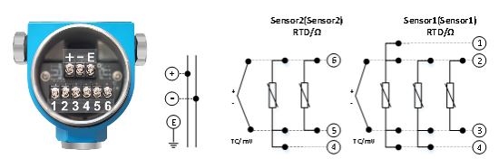
The overall hardware interface diagram of the temperature transmitter is shown in Figure 2.5
PA Intelligent Temperature Sensors Configuration
Topological Connection
A PROFIBUS PA network topology can have a variety of different structures, as shown in Figure 4.1Figure 4.2 shows the bus connection of the PA instrument. Both ends of the bus need to be connected to terminating resistors to ensure the quality of the bus signal. The bus has a maximum length of 1,900 m and can be extended to 10 km using a repeater.
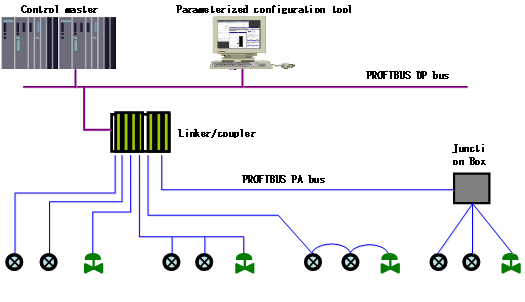
PROFIBUS PA network topology
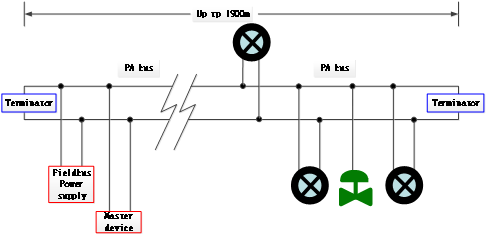
PROFIBUS PA bus connection
NCS-TT105 Intelligent Temperature Sensors Technical Specifications
1.1 Basic Parameter
Input Signal | Pt100、Pt1000、PT 200、PT500、CU50、CU100、0~500Ω、 0~4000 Ω; B E J K N R S T thermocouple, -100mV~100mV | |
RTD mode of connection | 2,3,4 wires connection | |
Power | FF/PA | (9~32)VDC |
HART | (11.5~45)VDC | |
Bus protocol | (4~20)mA+HART, FF, PA | |
Channels | 2 channels | |
Insulation | 1000VAC | |
Display | LCD LCD display or no display (optional) | |
Temperature Range | Operating temperature of the transmitter body: (-40~85) ℃ (no display) (-20~70) ℃ (with display) | |
Humidity Range | (5~95)%RH | |
Storage Temperature | -40 ~ 85℃ | |
Start Time | 5-Second Time (HART) 8-Second (FF, PA) | |
Refresh Time | The 0.8 ~ 1.3s depends on the type and wiring mode of the sensor | |
Damping Adjustment | Time constant of 0 to 32 seconds | |
Cold-end Temperature | ±0.5℃ | |
Alerting signal (only HART) | The alarm output can be set at 3.5 … 23 mA Upper / lower limit current 20.8mA / 3.7mA | |
Current accuracy (only HART) | 0.03% | |
Voltage Influence | ±0.005%/V | |
Ex Level | Ex ia IIC T4 Ga (developed according to this standard, not certified) | |
1.2 Technical indicators of thermal power resistance
RTD Accuracy (25℃)
Sensor type | Working range (℃) | Accuracy (25℃) | Heating drift (per ° C) |
Resistance | 0~500Ω | ±0.04Ω | ±0.001Ω |
0~4000Ω | ±0.35Ω | ±0.015Ω | |
PT100 | -200 ~ 850℃ | ±0.15℃ | ±0.003℃ |
PT 200 | -200 ~ 850℃ | ±0.15℃ | ±0.005℃ |
PT 500 | -200 ~ 850℃ | ±0.15℃ | ±0.005℃ |
PT1000 | -200 ~ 850℃ | ±0.15℃ | ±0.005℃ |
CU50 | -50 ~ 150℃ | ±0.15℃ | ±0.005℃ |
CU100 | -50~ 150℃ | ±0.10℃ | ±0.003℃ |
NCS-TT105 Intelligent temperature sensors field application

