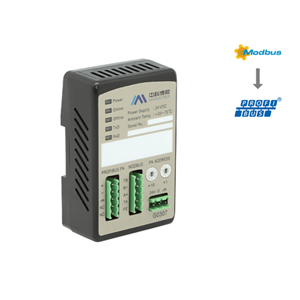
Modbus to PA Built-in Module

- Microcyber
- China
- In Stock
- 500 Sets/Month
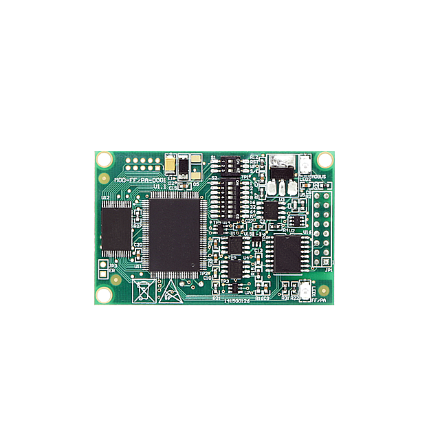
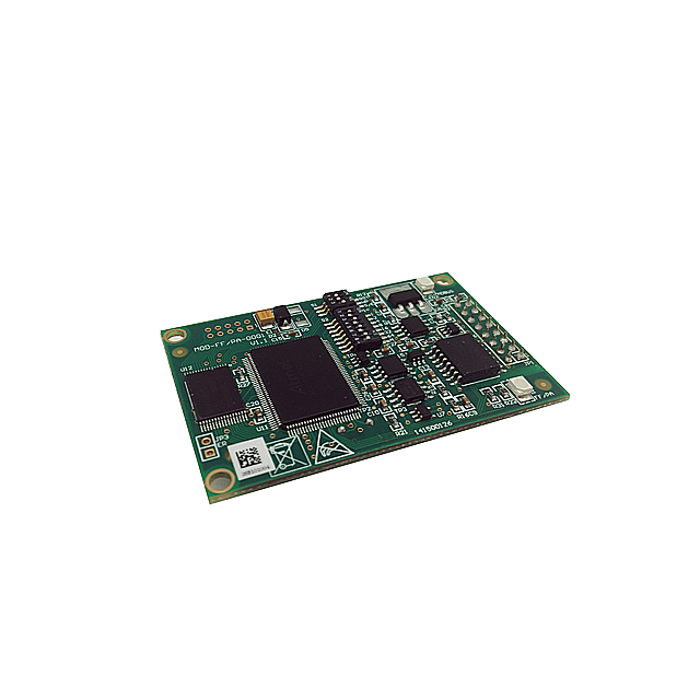
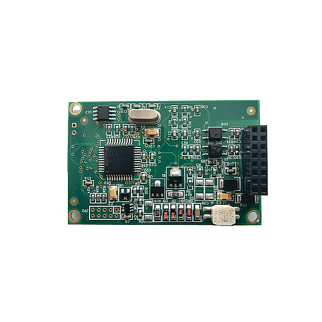
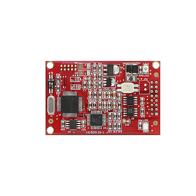
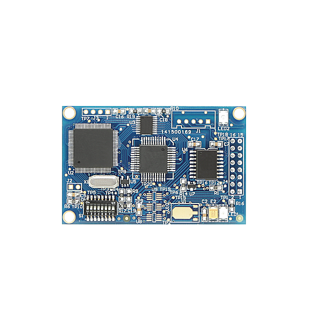
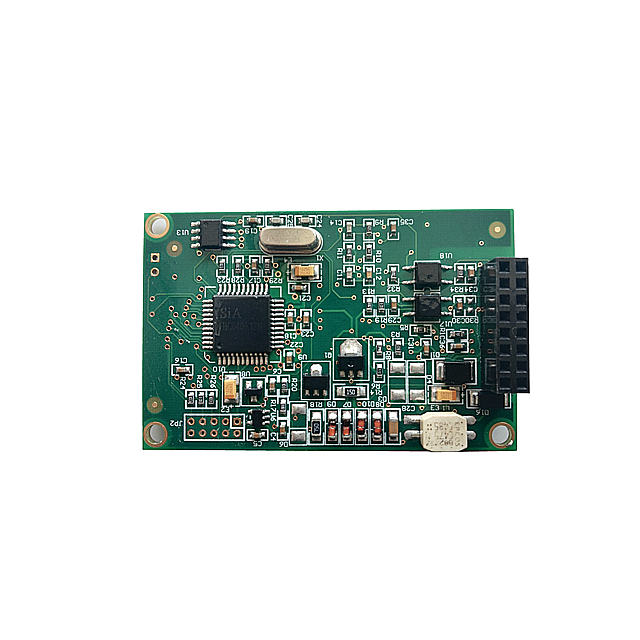
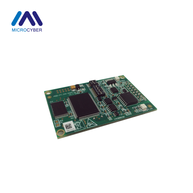
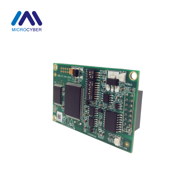
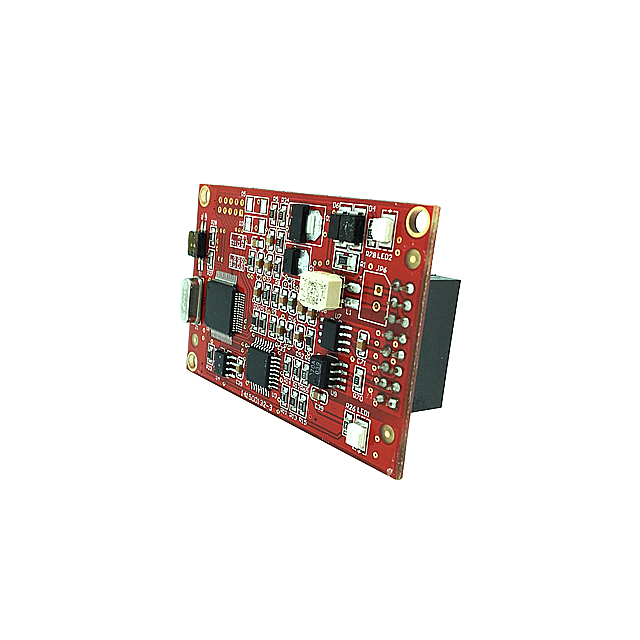
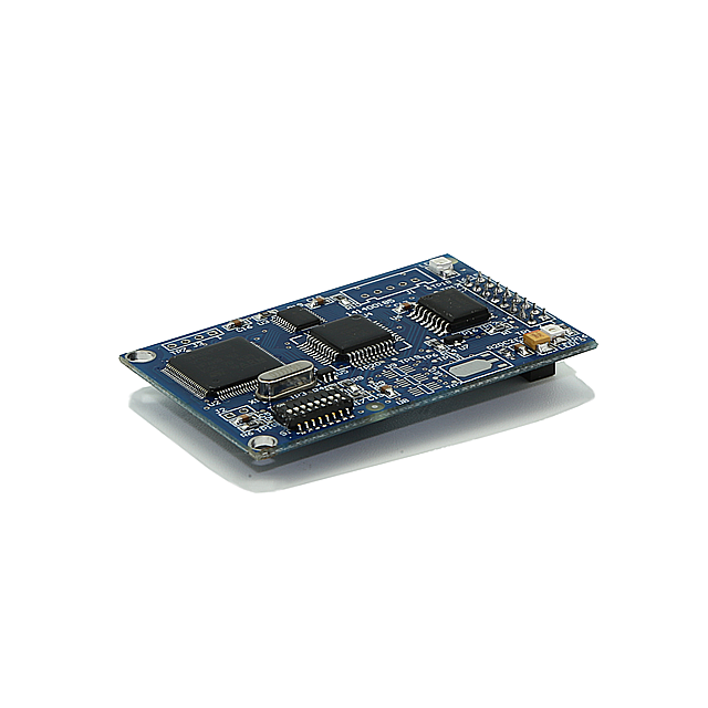
Modbus to PA built-in module is one of the Microcyber M-series built-in modules developed by Microcyber Corporation. This series of built-in modules have features like same size, same interface, easy to upgrade, easy configuration and so on, and Modbus to PA built-in module is the ideal choice for users to quickly develop the fieldbus equipment.
1. Size: 42mm*65mm
2. Comply with PA profile 3.02
3. Support Modbus-RTU communication parameters dynamic configuration
4. Support AI, AO, DI and DO function blocks
5. Support up to 4 channels AI, AO, DI, DO
Modbus to PA Built-in Module:By embedding the M0307 into the users' equipments with Modbus-RTU communication capabilities, the user equipment can be changed to Profibus PA slave station. User can quickly achieve Profibus DP, FF, HART & etc. equipment by replacing other modules of M series.
Modbus to PA Built-in Module Features
Same size
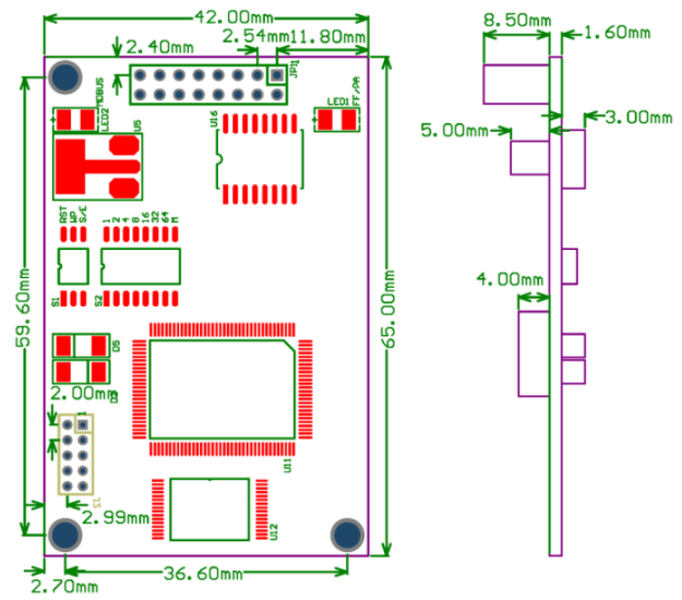
- - Microcyber M-series built-in modules have the same size, 65mm(length)*42mm(width).
Same interface
- - Microcyber M-series built-in modules adopt 2.54 spacing 16 pin connector, with compatible function.
Easy to upgrade
- - Replacement of Microcyber M-series different built-in modules can achieve different protocols of the device.
Simple configuration
- - Users can use Microcyber special configuration tool to configure, which is easy and convenient to operate.
Modbus to PA Built-in Module Product development process
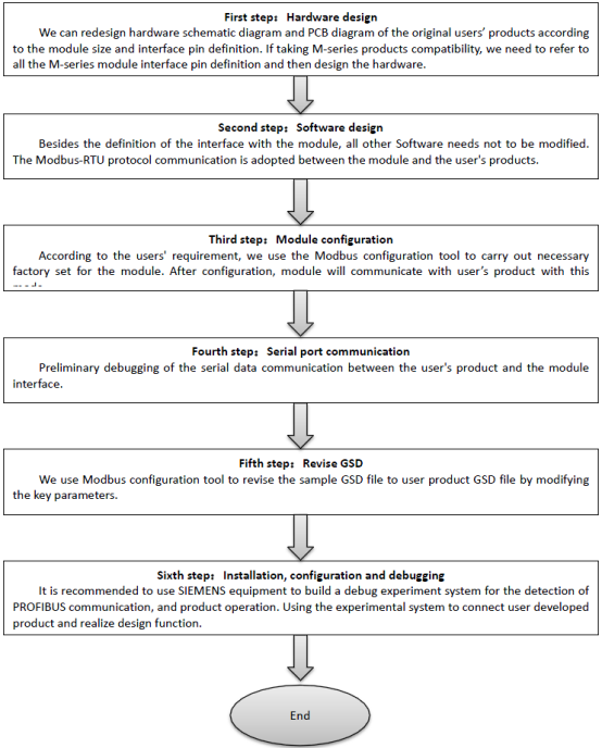
Modbus to PA Built-in Module Parameters
Technical Specification
Basic Parameter
Detection Object: Modbus RTU Slave
Bus Power: 9~32VDC
Current: ≤14mA
Protocol: Two-wire, PA
Isolation Voltage: Modbus and PA Interface, 500VAC
Temperature Range: -40℃~85℃
Humidity Range: 5~95%RH
Start-Up Time: ≤5s
Update Time: 0.2s
Performance Index
EMC: GB/T 18268.1-2010
GB/T 18268.23-2010
Physical Characteristic
Weight: 16g
Structure Material: Coating: Polyester Epoxy Resin
Default Communication Parameter
Slave Address: 1
Baud Rate: 9600
Data Bit: 8
Stop Bit: 1
Check: EVEN
CRC Check: Low Byte is Ahead
Support Modbus Function Code
1: Read Coils
2: Read Discrete Inputs
3: Read Holding Registers
4: Read Input Registers
5: Write Single Coil
6: Write Single Register
15: Write Multiple Coils
16: Write Multiple Registers
Modbus to PA Built-in Module Dimension
Outline Dimensions

Modbus to PA Built-in Module structure
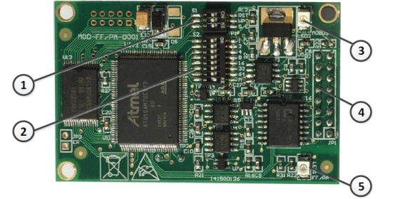

Modbus to PA Built-in Module Installation
Module external interface
The distribution and implication of the external interface of the M0307 Modbus to PA built-in
module is shown in picture:
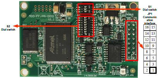
Communication interface definition
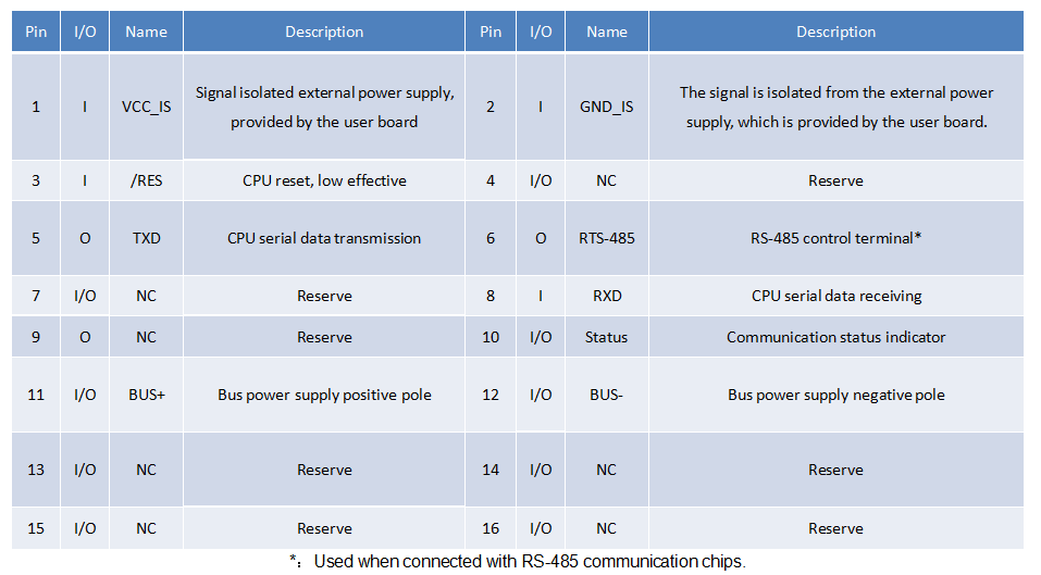
Modbus to PA Built-in Module User interface JP1 pin definition and description (16 pin connector)
The user interface JP1 provides the module one way signal isolated DC power supply. Also it provides a serial interface between the two boards, as well as the indicator light and other functions, the specific description is shown in table below.
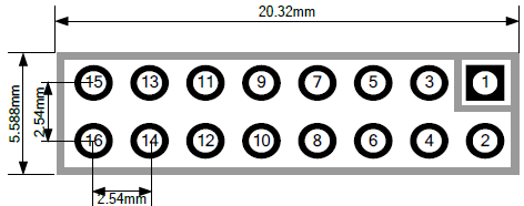
As shown in last picture, the user interface adopts 16 pin connector. The pins are defined as follows:
User interface pin definition
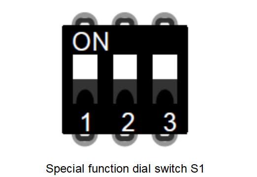
Special function dial switch S1
Special function dial switch S1 contains hardware reset, write protection, enabling the hardware to dial address etc.
Special Function Dial Switch S1 Description

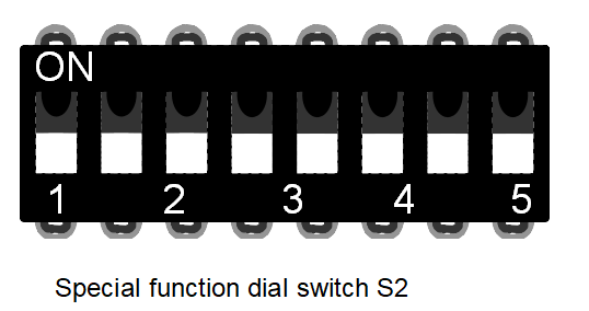
Special function dial switch S2
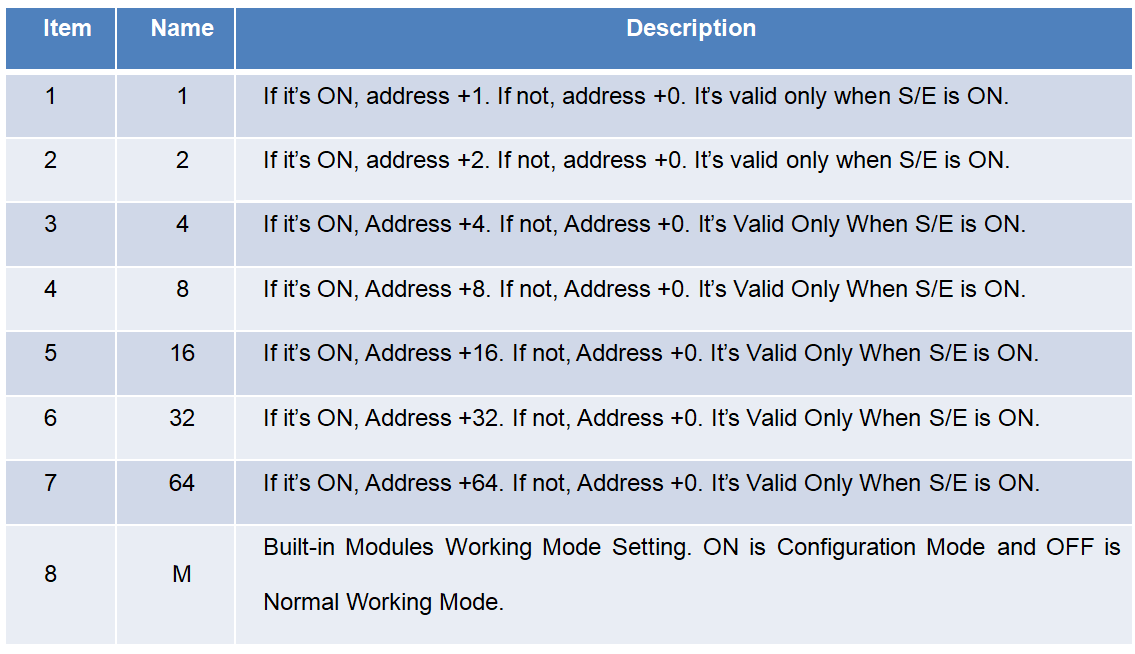
Special function dial switch S2 contains set Profibus address and working mode options.
Special function dial switch S2 description
Modbus to PA Built-in Module installation
M0307 has three Φ3 positioning holes. User can use 3 hexagonal prism with height 11mm to fix it to user board.
Modbus to PA Built-in Module Working principle
M0307 Modbus to PA built-in module is only one to one conversion module between Modbus and Profibus PA protocol. As a PA device, it can communicate with the Modbus device. Through configuration, it can achieve the interaction between Modbus device data and PA device data.
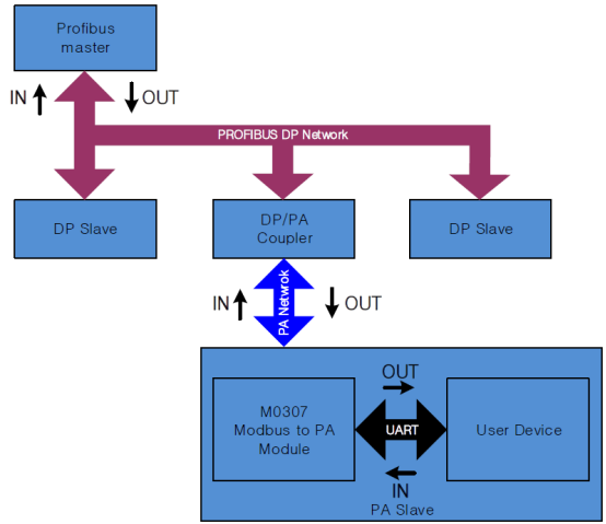
System connection chart
M0307 Modbus to PA built-in module contains 1 physical blocks, 1 transducer blocks, 16 function blocks, and
only 1 Modbus slave station.
The transducer block includes 4 analog input channels, 4 analog output channels, 4 discrete input channels
and 4 discrete output channels, totally 16 cyclic parameters. It also contains 10 floats, ten 32 bit integer, ten 16 bit
integer, ten 8 bit integer and two 32 byte string, totally 42 acyclic parameters.
The main function of the transducer block is to interact with the Modbus device.
Modbus to PA Built-in Module Working mode
M0307 can switch the two modes of operation by using the special function dial switch S2: configuration
mode and normal mode. ON is for configuration mode, and OFF is for normal mode.
Modbus to PA Built-in Module Configuration
Topology Structure
PA device supports a variety of network topologies, as shown in picture, it shows the bus connection of the PA device, and both terminals of the bus need to be connected to the terminal to ensure the quality of the signal. The maximum length of the bus is 1900 m, and the repeater can extend it to 10 km.
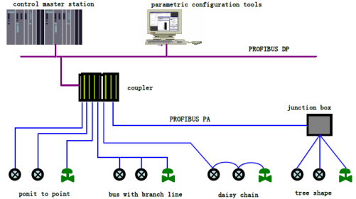
PA network topology
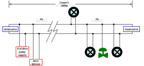
PA bus connection
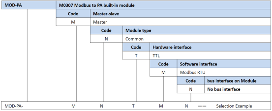
How To Choose M0307 Modbus to PA Module?
Modbus to PA Built-in Module FAQ
Q: How do I configure cyclic input and output parameter?
A: M0307 Modbus to PA Module includes analog input, analog output, discrete input and discrete output parameters. The number of parameters are fixed as four, so this chapter will introduce how these parameters and Modbus slave station associates. These 4 parameters all have read and write, data type, register address, function code and other attributes, which can be configured through the Modbus configuration tool.
Q: Can you provided OEM service?
A: Yes, we can, such as communication board, we can also provided fieldbus development toolkit.
Hot Products--Modbus to PA Built-in Module

