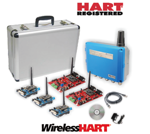
G1100 WirelessHART Smart Gateway

- Microcyber
- Liaoning, China
- In Stock
- 500 Sets/Month
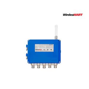
G1100 WirelessHART Gateway
1. Gain real-time process data. Reliability of wireless data can reach 99%
2. Modbus RTU/TCP, OPC & HART-IP connectivity
3. Comply with HART 7 protocol
4. Networks up to 250 devices
5. Class I, Division 2, Groups A, B, C and D T6
6. ATEX: II 3G Ex ec IIC T6 Gc
7. IECEx: Ex ec IIC T6 Gc
8. Explosion proof grade: Ex nA IIC T4 Gc
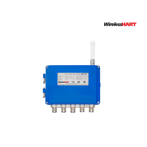
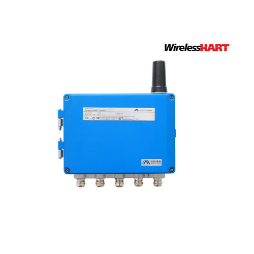
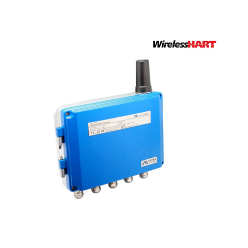
WirelessHART smart wireless gateway is in charge of establishment, management and maintenance of WirelessHART network, and network optimization, to make the devices in the network work in the effective and safe situation. Meanwhile WirelessHART smart gateway integrates device wireless information in the network to the PC system or data application, and provides related security assurance.
WirelessHART smart wireless gateway has the leading data reliability, network safety and advanced customer experience. It provides Web service for real-time network running check and data, without any restrictions. The engineer shall check abundant device status and device information in the Web service. And it provides total configuration function and the user may configure the device at any time and anyway.
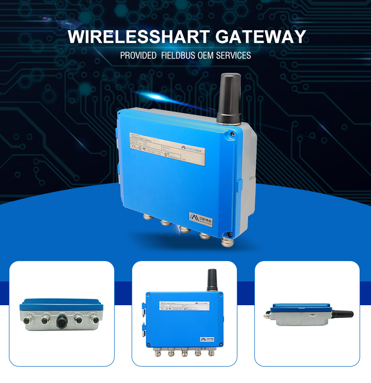
Including Goods |
WirelessHART smart gateway |
Fast guidance manual |
Metal installation accessories |
Network cable |
Prepare PC/Portable Computer
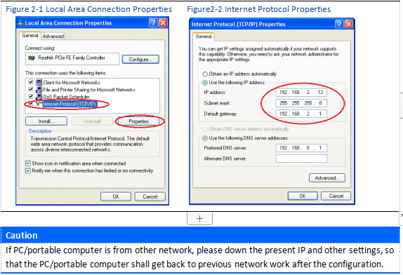
The user shall configure PC/portable computer before gateway communication, to establish a private network. The gateway setting shall be found in the PC/portable computer‘s control panel. Following are the methods:
1. Open “Network Connections”.
2. Choose “Local Area Connection”.
3. Click right click, choose “Properties” in the list.
4. Choose Internet Protocol (TCP/IP), and choose “Properties”.
Connection and Power On
With network cables provided together with gateway, connect one end of cable to Ethernet port of PC/portable computer, and connect the other end of Ethernet port of gateway, shown as the Figure below. After the connection between gateway and PC/portable computer, connect 24VDC (nominal value) power, at least 500mA to power input terminal of gateway.
Installation and Connection
Summary
The section is about how to install gateway and carry our electric connection correctly, including electric connection, ground and PC system connection.
General Considerations
Smart wireless gateway can be installed at any universal position. Please ensure the protection cover is ready, otherwise any electric device touch may bring in humility and pollution.
The gateway shall be installed in the place where is easy to connect PC system network (process control network) and wireless field network.
Physical Description
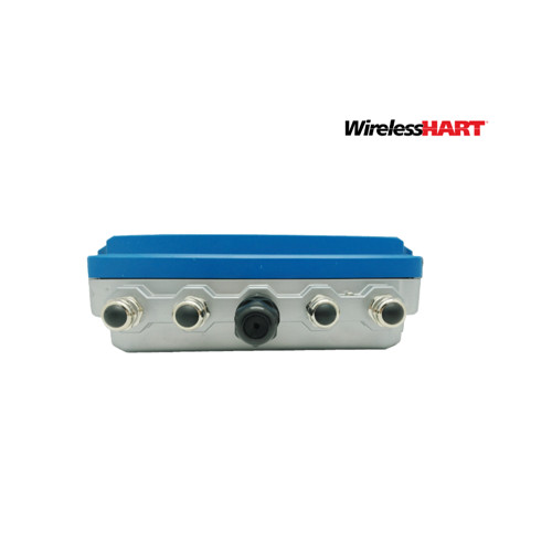
The dimension information is referred in Appendix A: Product Specification. Cast Aluminum covers gateway’s electric circuit. The user may operate electric device, wireless device and wiring terminals after opening the housing.
Installation
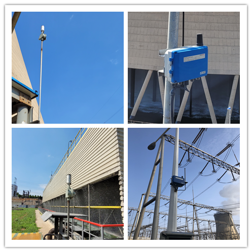
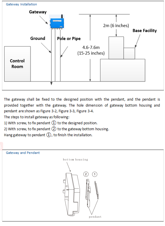
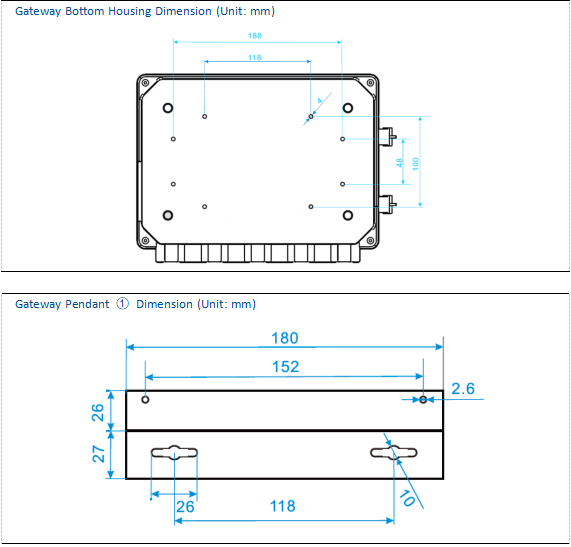
Find the best wireless performance for the gateway. Generally, the place is 4.6-7.6m (15-25 inches) high from the ground or 2m (6 inches) high from the base facility. Figure 3-1 is an
example for that.
Connection
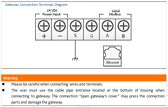
All the connections to gateway may be at the wiring terminals, the wiring terminal is inside the housing, and the wiring terminal label is inside the external housing. The standard wiring terminal label is shown in picture.

In junction box of external housing, there are five lead entrances for power wire and communication wire. Don't make power wire and communication wire together to pass lead pipe, or make the signal wire near the powerful electric device. Install lead pipe end cap at the new lead pipe port. In order to meet NEMA 4X and IP65 requirements, the user shall wind PTEE belt at external thread or smear sealant, to create watertight seal.
Ground
The gateway housing shall be grounded according to national and local electric specification. The most effective way is to connect gateway housing to the ground via minimum impedance. The user may also connect external ground terminal and ground to make gateway grounded. The impedance shall be no more than 1 Ω. The external ground terminal is at the bottom of the gateway, and it has the mark as following:

Ethernet
The gateway has a 10/100Based-TX Ethernet communication port. The connection is for access to gateway webpage and pass Modbus TCP and own protocol communication. For Ethernet connection, the user shall use Cat 5E type shield cable to connect Ethernet concentrator, interchanger or router. The maximum length of cable is no more than 100m (328 inches).
RS-485
The gateway assigns RS-485 (serial) connection. The user may assign the connection via A and B serial Modbus terminals, and the connection can be used for communication between RS-485 data bus and Modbus RTU. The user may use 18 AWG single STP to connect gateway and RS485 data bus. The bus length is no more than 1220m (4000 inches). The user shall connect Tx+ (positive pole, sending) and Terminal A, and connect Tx+ (negative pole, receiving) and Terminal B. The wiring shielded layer shall be shut and insulated, to prevent gateway housing to contact terminals of other ends. If 4-wire full duplex configuration is used for all the data bus, please change it into 2-wire half duplex configuration, according to picture.

Power
The gateway is powered by 24 VDC (nominal value), and requires at least 500 mA current. The positive and negative poles are connected to left side of terminal. The additional housing ground wire is under the housing.
The user shall connect the power to the positive pole + of wiring terminal and negative pole – of power terminal. The wiring shall be near gateway, and using external power cut-off switch and breaker.
Network Structure
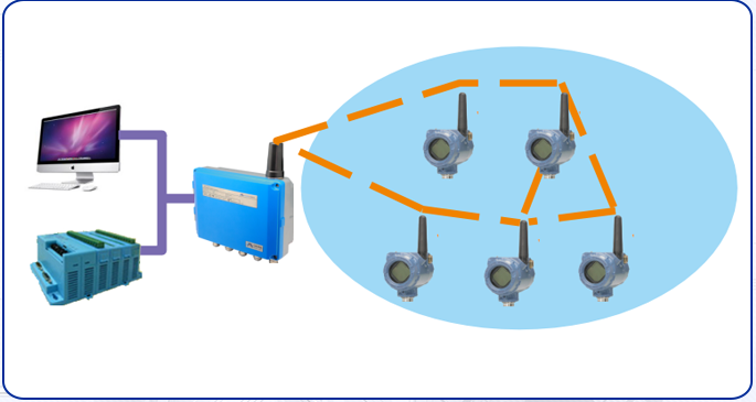
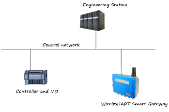
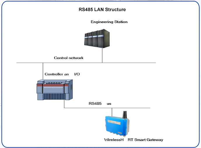
When the user is determining the network structure and protocol to integrate, the physical connection type is pretty important. Ethernet is the primary physical connection type, and RS485 can be used as the optional one. When the sub-gateway is sending integrate data to host system, and the network structure in Figure 4-1 is helpful.
If the user has higher security requirements, the user shall connect WirelessHART gateway to PC system via LAN (rather than WAN)
Ethernet
Ethernet connection supports Modbus TCP and private protocols. With this connection type, the gateway shall connect to control system via network interchanger, router or concentrator directly.
RS485 (Serial)
RS485 connection supports Modbus RTU protocol. With this connection type, gateway shall connect RS485 bus, the bus is generally connected with I/O board or Modbus I/O board.
Modbus
The gateway supports RS485 serial port’s Modbus RTU and Modbus TCP based on Ethernet. As a sub-device of Modbus network, polling by Modbus master device or client end (PC system) is requested.
Communication Setting
The communication setting in gateway shall set as the same as that of Modbus master device or client end. Choose “Setup” >”Protocol” in the gateway webpage, to enter Protocol Setting.
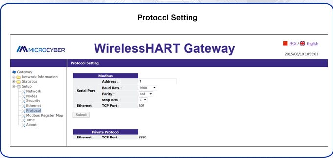
Address: The address is used by gateway for Modbus RTU communication, range 1~247.
Baud Rate: Serial Modbus RTU communication date ratio or speed, 1200~ 115200 bits/s supported.
Parity: The setting determination is used for failure check’s odd-even check of Modbus RTU communication. (none, even check or odd check)
Stop bit: The setting determination is used for numbers of stop bit of Modbus RTU communication information end. (1 or 2)
Click “Submit” and there will be “Restart the Gateway now?”, click “OK”. The gateway shall restart, and the setting is effective.
TCP Port: It is the TCP/IP port number for Modbus TCP (Ethernet), used by the gateway. The default value is 502.
