Cold Junction Compensation for Temperature Transmitters
People who work with thermocouples a lot may also not know exactly how the cold junction of thermocouple (reference) works. To be able to discuss the cold junction, we first need a brief understanding of thermocouple theory and how thermocouples work.
Cold Junction or Reference Junction
The thermocouple "cold junction" is often referred to as the "reference junction", but in our opinion people use the term "cold junction" more often .
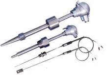
Common Thermocouples
Thermocouples are common temperature sensors in industry . Several advantages of thermocouples make them widely used. They can be used to measure very high temperatures, much higher than resistive temperature sensors (RTDs). A thermocouple is also very strong sensor, so it won't break easily. Although thermocouples are not as accurate as resistive temperature sensors, they are accurate enough in many applications .
How Thermocouples Work
Thermocouple consists of two wires made of different electrical conductors joined together at one end (the "hot" end), which is the end used to measure temperature. As Thomas Johann Seebeck discovered in 1821 , when the connection points of these wires are exposed to different temperatures, thermal current is generated, which creates small gap between the wires at the open ends. Voltage. The voltage depends on the temperature and the material of the wire used. This effect is called " Seebeck effect " .
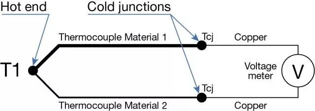
Simplified Schematic of Thermocouple
"Thermocouple Materials 1 and 2" in the above figure represent two different materials used for thermocouples. "T1" is the hot junction of the thermocouple, the point where temperature is measured. The two "TCJ" are the temperature of the cold junction. Because of the temperature gradient in the thermocouple wire , thermovoltage is always generated between the "hot" and "cold" ends. So, it's not the junction that creates the voltage, it's the temperature gradient along the wire that creates the voltage. But the explanation that thermal voltage is generated between the hot and cold terminals is easier to understand.
Thermocouple Types and Materials
There are many types of thermocouples manufactured from different materials and alloys. Different materials result in different sensitivities, produce different thermal voltages at the same temperature, and can affect other properties. Several different thermocouple types have been standardized and designations are given for the specified materials used. The name is usually very short, usually only one letter, such as K, R, S, J, K, etc. type.
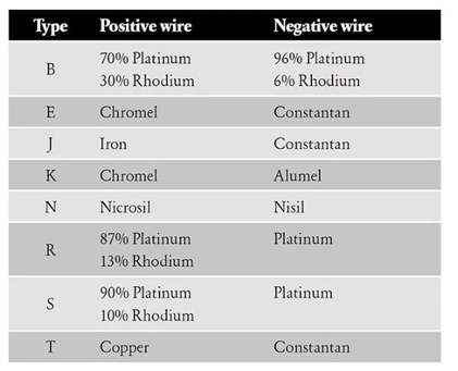
Most Common Thermocouples and Their Materials
Since different thermocouples are made of different materials, the thermoelectric voltages are also different, as shown in the figure below. At the same temperature, the voltage generated between different types varies greatly.
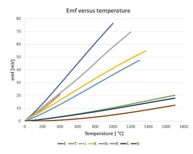
Thermal voltage of thermocouple
Seebeck coefficient of thermocouple
If you want to measure lower temperatures, the more sensitive types are obviously better as they provide higher voltages and are easier to measure. But if you need to measure high temperatures, you may want to choose some less sensitive types that can be used in extreme heat. The Seebeck coefficient indicates how much the thermocouple's voltage changes with respect to temperature. The graph above illustrates the different sensitivities between different thermocouples, and also explains why thermocouple calibrators often have different accuracy classes for different types of thermocouples .
cold end
We present simplified thermocouple schematic showing two dissimilar conductors connected together creating thermovoltage in " hot junction " connection. At this point, the big question you'll be asking should be " where's the other end of the wire ?" When you're measuring voltage from thermocouple, you connect the wires from the thermocouple to voltmeter . The voltmeter connection material is usually copper or gold plated copper, so it's not the same as the thermocouple material, which means you create two new thermocouples in the voltmeter connection!
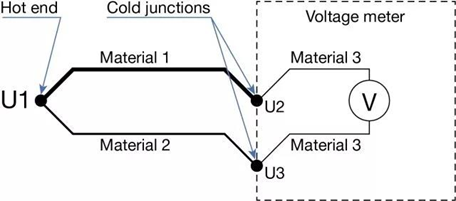
In the diagram above , Material 1 and Material 2 are the two thermocouple materials that form the thermocouple. The "hot end" is the point where they are soldered together, this is the point where the temperature of the process is measured and the point where the voltage U1 is generated. This U1 is what we want to measure. At the "cold junction" point, the thermocouple is connected to voltmeter whose connection is made of different material (Material 3). As long as these different materials are at the same ambient temperature, the additional voltages U2, U3 they generate have no effect on the overall thermal voltage . The thermal voltage in the index table is the voltage set generated by the thermal gradient from the hot end to the cold end when the cold end is at 0°C. However, in practical applications, the ambient temperature of the temperature transmitter and the cold junction of the thermocouple is not 0°C in most cases. Therefore, the influence of the cold junction temperature must be removed when calculating the hot junction temperature using an index table, which is also called cold junction compensation.
Cold Junction Compensation Method
1. Freezing point bath method
By their nature, thermocouple junctions do not develop any thermal voltage at 0°C (32°F). So, you can connect cold junctions at that temperature, for example in a freezing point bath or in a precise temperature calibration oven. Connect thermocouple wires to copper wires in freezing point bath without generating thermal voltage during the connection. Then you don't have to worry about the cold end. The connections need to be electrically isolated from the water in the ice bath to avoid any leakage currents that could cause errors or possible corrosion. This is a very precise method and is usually done by calibration laboratories. In factories, this is not very practical, so it is not usually used in factories.
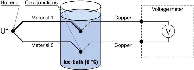
2. Cold Junction at Fixed Temperature
Since ice sinks have been found to be impractical, you can also do the cold junction at a known, fixed temperature. A small junction box can be used, which has a temperature control device to keep the junction box at a certain temperature at all times. Typically, the temperature is higher than ambient, so the box only needs to be heated, not cooled.

When you know the temperature at the cold junction and the type of thermocouple, you can calculate and compensate for the thermal voltage at the cold junction. Many measuring devices or temperature calibrators have the ability to enter the cold junction temperature and the device will do all the calculations and compensations for you.
3. Automatic compensation for measuring cold junction temperature
Leave it to the measuring equipment to calculate automatically. The measuring device (transmitter, DCS input card) can measure the cold junction temperature at any time, and automatically compensate the cold junction error online. Since the measuring device also knows the type of thermocouple, compensation can be performed automatically and continuously.
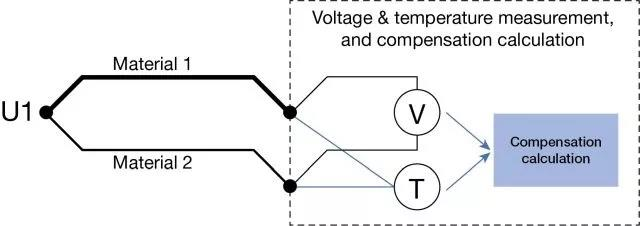
This is necessarily the easiest and most practical way to compensate for cold junctions in normal measurements and calibrations, since you don't need to worry about the cold junction, but let the equipment handle it.
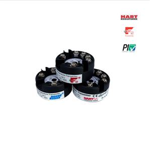
Cold Junction Compensation for NCS-TT106
The modular temperature transmitter products of Microcyber Corporation include HART, PROFIBUS PA, FF H1 three agreements.
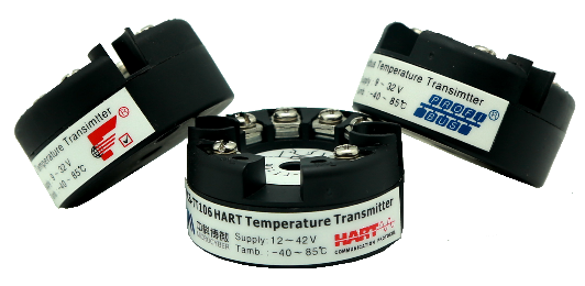
Support all the cold junction compensation methods mentioned above, and there are two methods of automatic compensation for measuring the cold junction temperature. You can choose to use the built-in temperature sensor close to the terminal of NCS-TT106, or you can choose an external platinum resistance temperature sensor. The temperature measurement accuracy of the built-in temperature sensor is ±0.5 ℃ , and when the external PT100 platinum resistance temperature sensor is connected, the temperature measurement accuracy is ±0.15 ℃ .

