Modbus to FF Built-in Module

- Microcyber
- China
- In Stock
- 500 Sets/Month
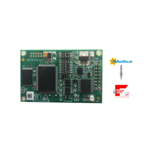
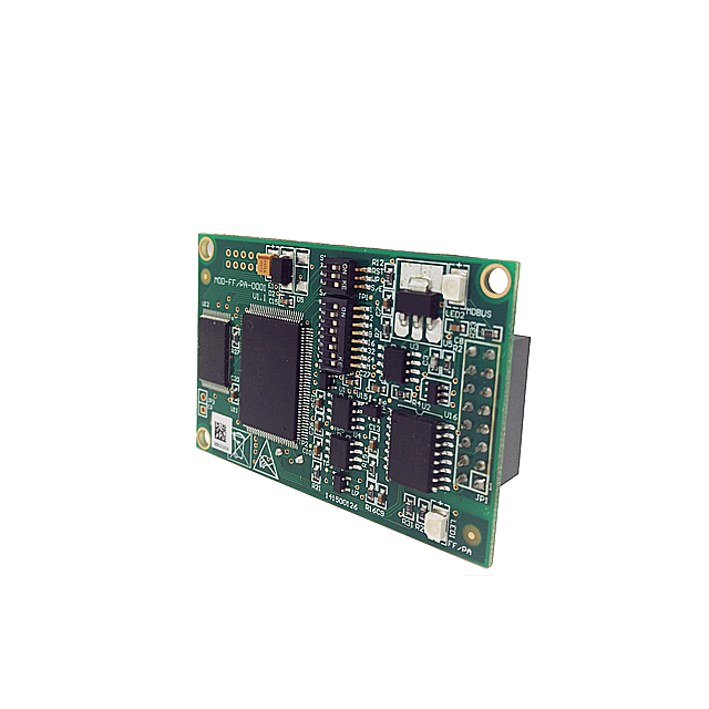
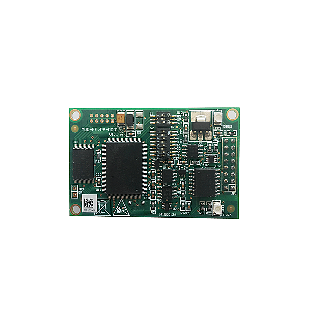
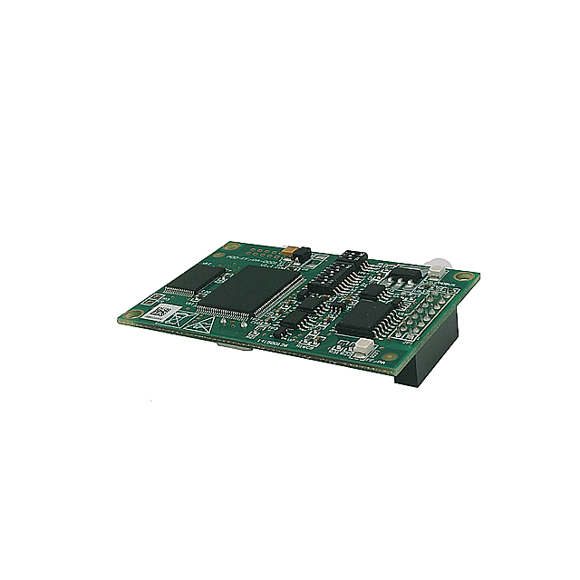
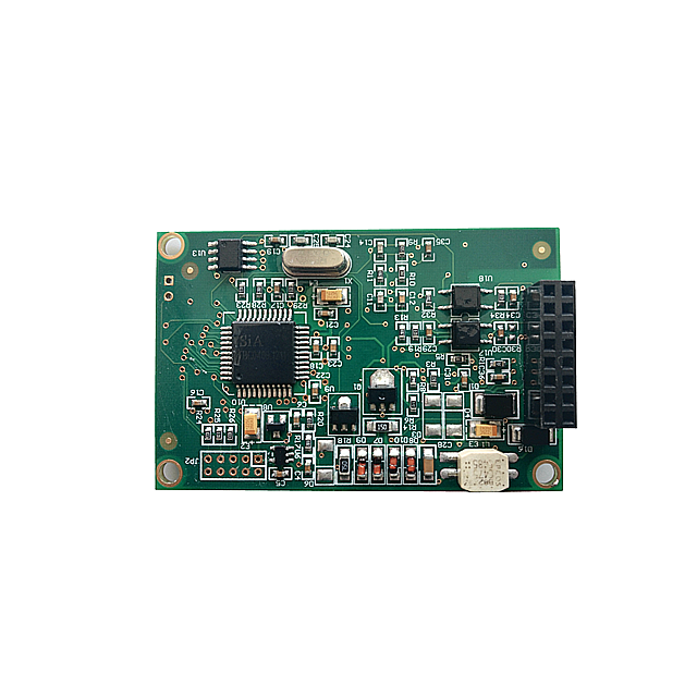
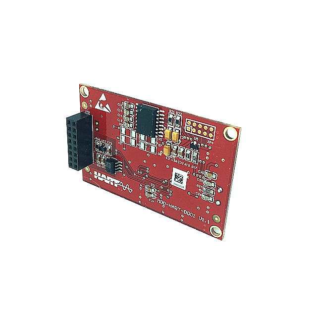
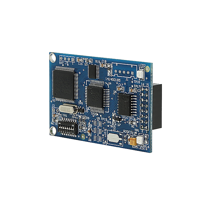
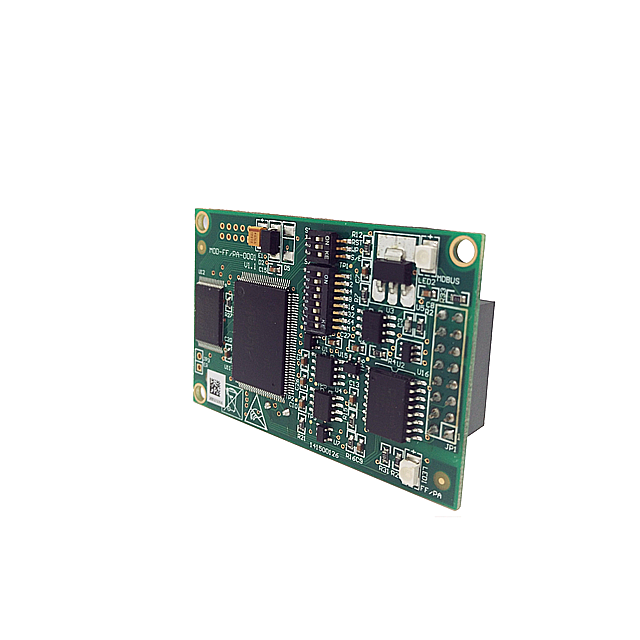
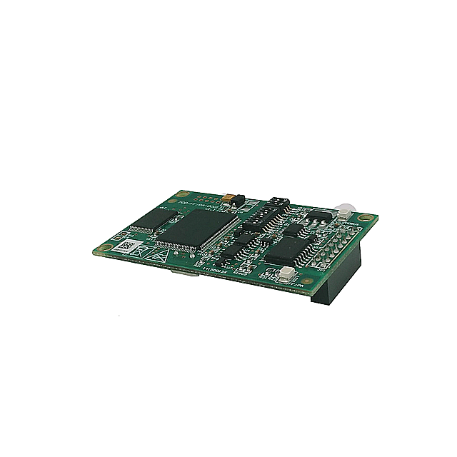
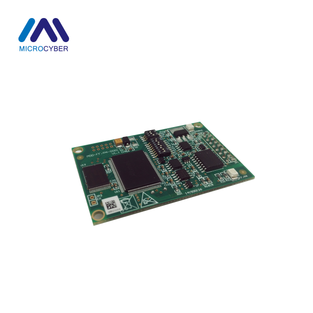
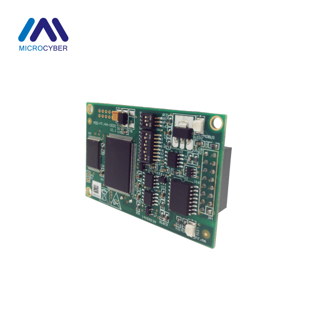
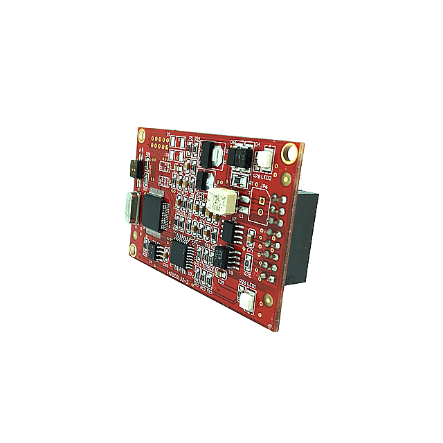
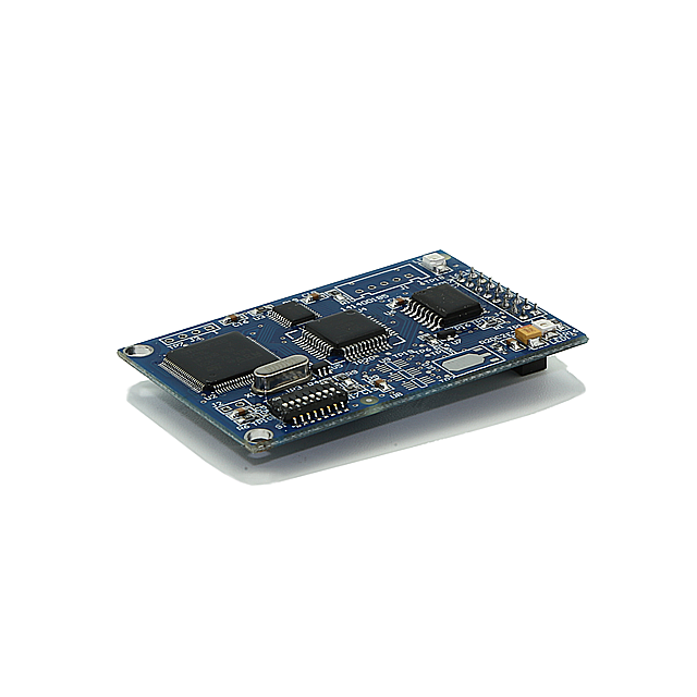
Modbus to FF Built-in Module realizes the conversion function from MODBUS Protocol to Foundation Fieldbus F1 Protocol. Modbus to FF Built-in Module is one of the Microcyber M-serise modules,which have features of same size,same interface,easy to upgrade and easy to configure
Modbus to FF Built-in Module:
Modbus to FF Built-in Module is an ideal choice for user to develop fieldbus devices. As Modbus master station,M0313 Modbus to FF module communicates with Modbus-RTU device via TTL interface, and it can convert the data of Modbus-RTU device to FF device variable output.
Modbus to FF Built-in Module Features
Same Size
- - The Microcyber M series built-in modules have the same size: 65mm(length)*42mm(width)
Same Interface
- - The connector of Microcyber M series built-in modules is 2.54 pitch 16 pin, function of them are compatible.
Easy to Upgrade
- - Please replace the different kind of Micrcyber M series modules to realize the different protocols of devices.
Easy to configure
- - Please use the special tool provided by Microcyber Corporation for configuration,it is easy to operate .
Comply with FF protocol standard
Support Modbus-RTU communication parameter dynamic configuration
Support function blocks: Al, AO, DL, DO, PID, etc
Support ITK6.1.1
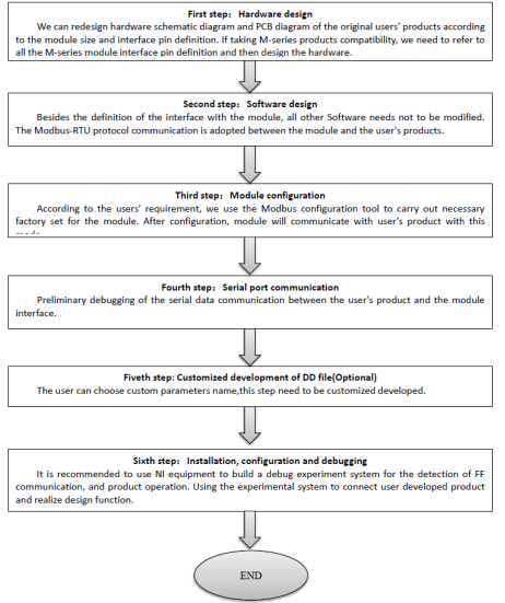
Modbus to FF Built-in Module Product Development Process
Modbus to FF Built-in Module Parameters
Technical Specification
Basic Parameters
Measure Object: Modbus RTU slave device
FF Bus Power: 9~32VDC
Quiescent current: ≤14mA
Bus Protocol: Two-wire, FF Protocol
Insulating Voltage: Modbus and FF Bus Interface, 1000VAC
Temperature Scale: -40℃~85℃
Humidity Scale: 5~95%RH
Start Time: ≤5s
Refresh Time: 0.2s
Modbus to FF Built-in Module Performance Index
Electromagnetic Compatibility:
Meet GB/T 18268.1-2010
Test Method for FF Port Meets GB/T 18268.23-2010
Modbus to FF Built-in Module Physical Properties
Weight: 16g
Structural Material Coating: Polyester Epoxy Resin
Modbus to FF Built-in Module Default Communication Parameters
Slave Address: 1
Baud Rate: 9600
Data Bit: 8
Stop Bit: 1
Calibration: EVEN
CRC Calibration: Low Byte Ahead
Modbus to FF Built-in Module Supportive Modbus Function Code
1: Read Loop Status
2: Read Discrete Input Status
3: Read Keeping Register Value
4: Read Input Register Value
5: Write Loop
6: Write Single Register Values
15: Write Multiple Loop
16: Write Multiple Register Values
Modbus to FF Built-in Module Dimension
Modbus to FF Built-in Module Outer Size Diagram
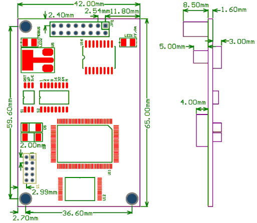
Outer size of built-in module(Unit:mm)
Modbus to FF Built-in Module Structure Diagram
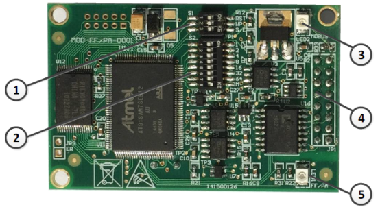
Whole structure of built-in module

Modbus to FF Built-in Module Installation
External Interface
M0313 Modbus to FF built-in modul’s terminal distribution and meaning is shown as picture:
M0313 Modbus to FF built-in modul's terminal distribution and meaning
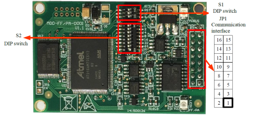
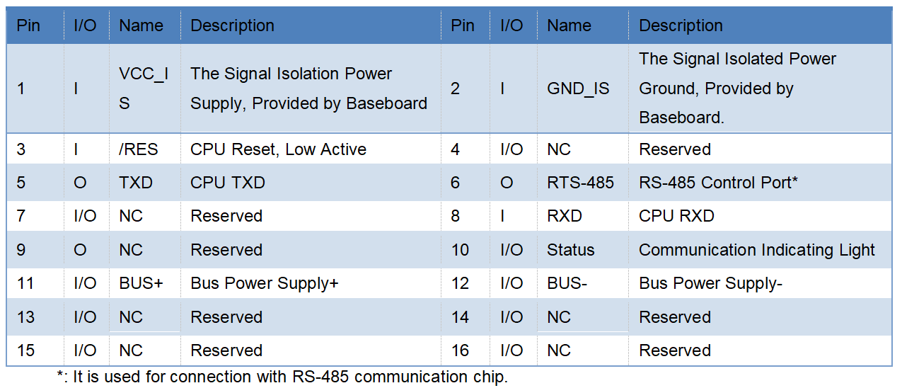
Modbus to FF Built-in Module Communication interface JP1
JP1 Communication interfac's meaning is shown as below:
Modbus to FF Built-in Module Configuration of DIP Switch
There is a 3-position DIP switch S1 and a 8-position DIP switch S2 for M0313 Modbus to FF built-in module, shown as picture.
The description for DIP switch S1 is shown as below:

Modbus to FF Built-in Module Installation of Module
There are three Φ3 location hole in the module.The module can be fixedly installed in the user’s board with three hexagonal prism.
Modbus to FF Built-in Module Working Principle
M0313 Modbus to FF built-in module is a module supporting Modbus and FF protocol.As FF device,it can communicate with Modbus devices,read Modbus data to FF device by simply configuration,and transfer data to control system through FF bus.

System Wiring Diagram of M0313 Modbus to FF built-in module
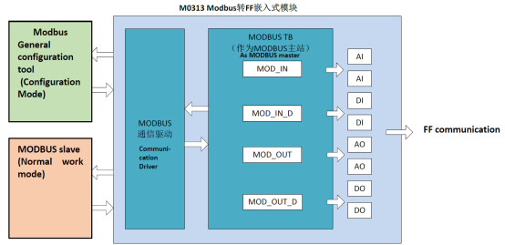
M0313 Modbus to FF built-in module support 1 Modbus slave device,8 groups of analog input output and discreter input output parameters,totally 32 channels provided.It configures Modbus device’s data into transducer block’s parameters via Modbus register,and provides data support for FF system via channels between variables and AI,AO,DI and DO function blocks.Principle Diagram for Modbus to FF built-in module is shown in picture:
M0313 Principle Diagram for Modbus to FF built-in module
Modbus to FF Built-in Module Configuration of module
Topologic connection
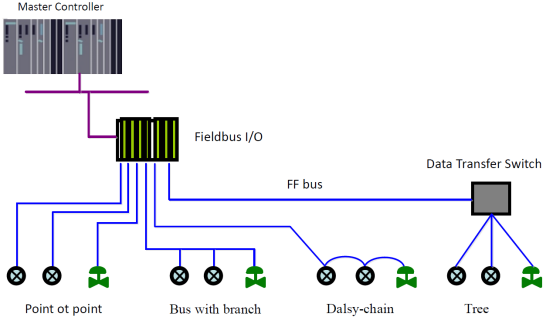
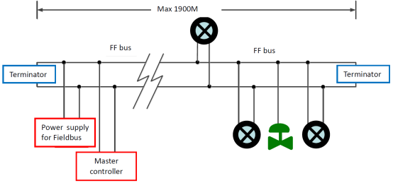
FF device support many net topologies shown as picture. The bus connection of FF instrument is shown in picture, in order to ensure the bus signal quality, the terminal matching resistances should be connected to the 2 ends of the bus.The bus maximum length is 1900m, with a repeater, the legth can be extended to 10 kilometers.
Topology of FF Bus
FF bus connection
How To Choose M0313 Modbus to FF Module?
Modbus to FF Built-in Module FAQ
Q: Can I get a free electronic manual?
A: Yes, if you want it, please contact us.
Q: How many Function block dose M0313 Modbus to FF Module have?
A: Default configuration of Modbus to FF built-in module has 1 RES function block, 4 for each AI, AO, DI, DO, PID function block and Modbus transducer block (Modbus_TB)complying to FF specifications.AI, AO, DI, DO respectively supports 8 channels(CHANNEL), channel is corresponding to analot/discrete input and output parameters of Modbus transducer block.
Q: Can you provided OEM service?
A: Yes, we can, such as communication board, we can also provided fieldbus development toolkit.
Hot Products--Modbus to FF Built-in Module

